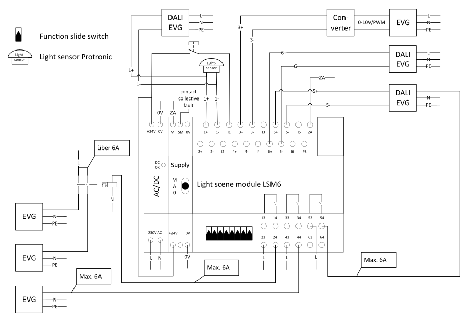
Circuit diagram
Operation of LSM6
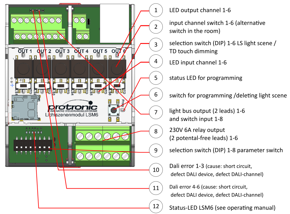
Verifying of the hardware settings on LSM6
DIL-switch on the channel
Please check that the DIL switches for channels 1 to 6 are correctly set to the desired mode:
– LS for light scene operation,
– TD for touch-dimming operation.
Parameter swith
Please ensure that the channels can respond to the desired signals (touch/switch signals). The parameter switch 3 (for channels 1-3) and the parameter switch 4 (for channels 4-6) should be set to
– ON to process switch signals (e.g. GLT) and to
– OFF to process touch signals.
For more details, see the chapter on “Parameter Switch” in the manual.
SD-card
Please make sure that an SD card is inserted for the desired configuration on the device. If no SD card is present, the configuration will be done directly through the device’s internal memory.
Test before start up
General information
Before applying power to the device and putting it into operation, we recommend conducting a test to ensure correct connection of the bus participants.
The outputs of the device should not be connected to the adjacent inputs, as the 24V of the input side can result in destruction of the outputs or false signals.
The bus participants of the individual channels 1-6 must be properly connected to each other:
- Connect the bus participant with the Dali+ / Dali- to the respective channel on the LSM6
- No additional connection with 24V on Dali+ / Dali-
- No connection between the channels
- No conncetion between 2 bus participants of different channels.
Bus participants should not be connected across channels. This can also result in destruction of the device’s outputs. Therefore, the following test sequence is recommended.
Step 1 – voltage test
The individual Dali channels can be checked for proper wiring using the parameter switch (DIL8 on ON). Activate the Dali channel via the switch on the device, a voltage of max. 20V should be measured at the corresponding outputs (Dali+/-). When inactive, 0V should be measured at the Dali channel.
If deviations are measured, disconnect all bus lines (outputs on the device). No voltage should be present on the disconnected cables of the channels.
Step 2 – continuity test
Short-circuit all the buses, except for one, (connect Dali+/-). Measure this non-short-circuited bus, there should not be any continuity. If continuity exists, it is assumed that the participants are connected across channels. This needs to be corrected.
Diagnosing and fixing errors
Bus channel is damaged.
This can be due to one of the above reasons, find and fix the error. Instead, use another unused bus channel if you have one.
Bus participant channel x is switched by input y.
Is the light scene correctly configured (i.e. channel x and y are not active in a light scene)? Then it indicates a connection of the bus cables of different channels. This needs to be corrected. If necessary, the bus channel is damaged or gives false signals.
Further information on function, settings and parameterisation
You can find a general description of the functioning of the lighting control in the operating manual on our website: https://protronic-gmbh.de.
Safety instructions
The personnel must read and understand the operating manual before starting any work. It contains important information that protects the operator from potential dangers or explains content-related connections. Please note the warning and safety instructions in the operating manual – LSM6 operating instructions.